


 Annex
Annex

Introduction
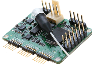
Rofea’ modulator bias controller is specially designed for Mach-Zehnder modulators to ensure a stable operation state in various operating environments. Based on its entirely digitized signal processing method, the controller can provide ultra-stable performance.
The controller injects a low frequency, low amplitude dither signal together with a bias voltage into the modulator. It keeps reading the output from the modulator and determines the condition of the bias voltage and related error. A compensate bias voltage will be applied afterward according to the various pre- measurements. In this way, the modulator is ensured to work under a proper bias voltage.
The controller is very compact in volume with high performance. The maximum stable DC extinction ratio measured in Lab is 50.4dB. The highest carrier suppression ratio measured is 43dB.
Feature
• MZM bias control on Null and Peak modes
• Low profile: 37mm(W) × 25mm(D) × 8mm(H) High extinction ratio:
53dB Maximum1
50.4dB DC extinction ratio lab-verified 2
43dB carrier suppression lab-verified
• Low dither amplitude: 0.1% Vπ
• High stability: with fully digital implementation Easy to use:
Manual operation with mini jumper Flexible OEM operations through UART3
Two different modes to output bias voltage:
a. Automatic bias voltage
b. User-defined bias voltage
Application
• LiNbO3 and other MZ modulators
• Brillouin scattering system and other optical sensors
• Radio over Fiber systems
• Pulse Generation
• Carrier Suppression
Specifications
Parameter
Min
Typ
Max
Unit
Control Performance
Extinction Ratio
MER1
53
dB
Stabilization time
10
s
Electrical
Positive power voltage
+14.5
+15
+15.5
V
Positive power current
20
30
mA
Negative power voltage
-15.5
-15
-14.5
V
Negative power current
1.5
4
mA
Output voltage range
-11.34
+11.34
V
Output voltage precision
350
µV
Dither frequency
999.99
1000
1000.01
Hz
Dither amplitude
0.1%Vπ
V
Optical
Input optical power2
-30
-9
dBm
Input wavelength
1100
1650
nm
1 MER refers to Modulator Extinction Ratio. The extinction ratio achieved is typically the extinction ratio of the modulator specified in the modulator datasheet.
2 Please be noted that the input optical power does not correspond to the optical power at the selected bias point. It refers to the maximum optical power that the modulator can export to the controller when the bias voltage ranges from −Vπ to +Vπ.