


 Annex
Annex

Introduction
An IQ modulator consists of three different modulators: I, Q arms are intensity modulators, Parm is a phase modulator. The IQ modulator is typically applied to coherent transmission systems. Rofea'modulator bias controller is specially designed for IQ modulators to ensure a stable operation state in various operating environments. Based on its entirely digitized signal processing method, the controller can provide ultra-stable performance.
The controller injects a low frequency, low amplitude dither signal, and a bias voltage into the modulator. It keeps reading the modulator's output and determines the condition of the bias voltage and the related error. A compensate bias voltage will be applied afterward according to the previous measurements. In this way, the IQ modulator is ensured to work under a proper bias voltage.
The controller is very compact in volume and is suitable for modern communication systems.
Feature
• Provides three biases for IQ modulators Modulation format-independent:
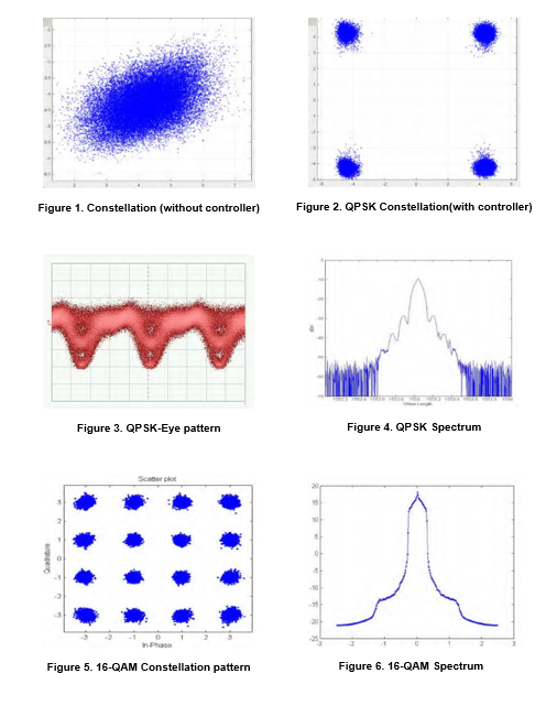
QPSK, QAM, OFDM, SSB verified
Plug and Play:
No manual calibration needed Everything automatic
I, Q arms: control on Peak and Null modes High extinction ratio: 50dB max1
• Parm: control on Q+ and Q- modes Accuracy: ± 2◦
• Low profile: 40mm(W) × 28mm(D) × 8mm(H)
• High stability: fully digital implementation Easy to use:
Manual operation with mini jumper Flexible OEM operations through UART2
Two modes to provide bias voltages: a.Automatic Bias Control b.User-defined bias voltage
Application
• LiNbO3 and other IQ modulators
• QPSK, QAM, OFDM, SSB, etc
• Coherent Transmission
Ordering Information
Part No.:R-BC-IQ-03
Contact: sales@rof-oc.com
1 The highest extinction ratio depends on and cannot exceed the system modulator maximum extinction ratio.
2 UART operation is only available on some version of the controller
performance:
Specifications
Parameter
Min
Typ
Max
Unit
Controll Performance
I, Q arms are controlled on Null(Minimum) or Peak(Maximum) point
Extinction ratio
MER1
50
dB
P arm is controlled on Q+(right quadrature) or Q-( left quadrature) point
Accuracy at Quad
−2
+2
degree2
Stablization time
15
20
25
s
Electrical
Positive power voltage
+14.5
+15
+15.5
V
Positive power current
20
30
mA
Negative power voltage
-15.5
-15
-14.5
V
Negative power current
8
15
mA
Output voltage range
-14.5
+14.5
V
Dither amplitude
1%Vπ
V
Optical
Input optical power3
-30
-8
dBm
Input wavelength
1100
1650
nm
1 MER refers to intrinsic Modulator Extinction Ratio. The extinction ratio achieved is typically the extinction ratio of the modulator specified in the modulator datasheet.
2 Let Vπ denote the bias voltage at 180◦ , and VP indicates the most optimized bias voltage at Quad points. Then the controller bias voltage output will be in the range of VP ± 2◦ Vπ 180◦
3 Please be noted that the input optical power does not refer to the optical power at the selected bias point. It is the maximum optical power that the modulator can export to the controller when the bias voltage ranges from −Vπ to +Vπ.