
High stability electro - optical modulator
1、 product description
High stability electro-optical modulator is a highly integrated product That integrates electro-optical intensity modulator, bias point automatic control board, microwave amplifier, and driving circuit, switching power supply, and others into one part. This product has low insertion loss, high working bandwidth, low half Wave voltage, stable output signal, not affected by the external environment and other characteristics, the meanwhile electro-optical modulator can work on the QUAN +/-, NULL and PEAK point long-term stably for long-term, so it is widely used in high-speed optical transmission equipment, microwave photon links, phased array and other fields. And the product design for the desktop standard 1U chassis, being used in factories, laboratories, research institutes, and other applications, and what can customize the outlook to meet the needs of different applications.
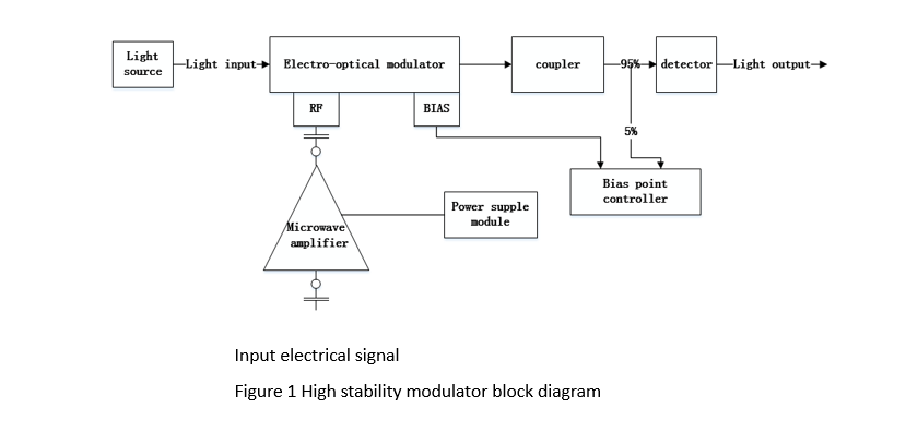
High stability electro-optical modulator is composed of the light source module, electro-optical intensity modulator, microwave amplifier and drive circuit, and bias control board composition. The block diagram is shown in figure 1.

① operating wavelength : 1550nm( 850nm、1064nm)
② insertion loss: 3~5dB
③ optical fiber type : PMF/SMF
④ optical interface: FC/PC、FC/APC
① -3dBbandwidth : 10GHz(2.5GHz、20GHz、40GHz)
② cut-off frequency: 75KHz
③ electrical return loss : -12~-10dB
④ input impedance : 50Ω
⑤ input signal amplitude : 100~500mV
⑥ the range of adjustable gain: 0~24dB
⑦ adjustment accuracy: 0.5dB
⑧ bias voltage adjustment range : -7~7V
⑨ adjustable accuracy: 0.1V
⑩ power interface : SMA(f)(K(f)、V(f))
① laser wavelength : 1550nm(850nm、1064nm)
② output optical power : 10-20dBm
③ 3dBspectral width : 2MHz
④ power stability : ±0.005dB/5min ±0.01dB/8h
AC power :AC220V/50Hz
Storage temperature :-40℃~70℃
he front panel interface and display definition are shown in table 1
|
Name |
Form |
Definition |
|
Switch |
Self-locking switch with light |
Instrument mater switch |
|
RF input |
SMA(F) |
RF signal input |
|
Light input |
FC/APC |
Light source input side |
|
Light output |
FC/APC |
Light source output side |
|
Linear area |
Switch |
- |
|
Extreme point |
Switch |
- |
|
+ |
Switch |
- |
|
- |
Switch |
- |
|
Gain p |
Switch |
Adjust gain |
|
Gainq |
Switch |
Adjust gain |
|
Display |
1602C |
Display RF amplified signal |
※remark :the lowest point is null point
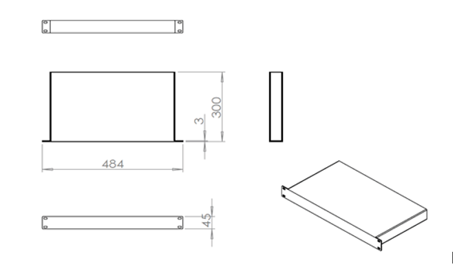
dimensions :484mm×300mm×45mm(tolerance:±1.5mm)
dimensional drawings are shown in figure 3

Figure 3 high-stability electro-optical modulator size chart
Name: high stability electro-photonic modulator
1.test conditions room temperature 25±2°C;
2. relative humidity 45%。
Test data
|
Name |
Symbol |
Unit |
Technical indicator |
Measured value |
|
Insertion loss |
IL |
dB |
<5 |
3.8 |
|
-3dB bandwidth |
S21 |
GHz |
10 |
11.2 |
|
Light return loss |
ORL |
dB |
-40 |
-40 |
|
Electrical return loss |
S11 |
dB |
-12 |
-12.5 |
|
RF gain |
G |
dB |
24 |
24 |
General parameter
|
Name |
Symbol |
Unit |
Value |
|
Operating wavelength |
l |
nm |
1520-1560 |
|
RF input impedance |
|
Ω |
50 |
|
Input signal amplitude |
|
mv |
|
|
Input optical fiber |
|
|
PMF |
|
Output optical fiber |
|
|
SMF-28 |
|
Input optical fiber interface |
|
|
Slow axis alignment |
|
Output optical fiber interface |
|
|
FC/APC |
|
RF interface |
|
|
SMA(F) |
limit parameter