
Test method for half-wave voltage of lithium niobate
The half-wave voltage is one of the important indicators of the lithium niobate electro-optic modulator. It refers to the voltage required to change the phase by π, usually expressed as Vπ. However, the detection of the phase of light in optics has always been a difficulty because the phase is not easily measured directly. Therefore, the detection of the phase is usually converted into a detection of a physical parameter that is easily measured directly for light intensity, frequency, and the like. At present, there are several commonly used methods for measuring half-wave voltage, namely optical communication analog method, frequency multiplication modulation method and extreme value measurement method.
The optical communication analog method converts the modulated signal into a sound signal, and connects the sound player to the external input. When the modulated sinusoidal signal is cut off, the output signal is played through the speaker of the power output port, and the volume is controlled by the demodulation amplitude. During the gradual increase of voltage, the sound will appear twice the volume and distortion, and the difference between the two voltages is the measured half-wave voltage. The advantage of this method is that the measurement is simple, but since the judgment of the minimum value during the measurement is too rough, the accuracy of the measurement data is not high.
The basic principle of the frequency doubling modulation method is to simultaneously load the DC voltage and the AC signal. When the DC voltage is adjusted to the voltage value corresponding to the extreme value of the output light intensity, the output AC signal will exhibit frequency doubling distortion, corresponding to the frequency doubling distortion. The difference between the DC voltages is the half-wave voltage.
The basic principle of the extreme value measurement method is that the modulation signal is not loaded on the phase modulator, only one DC voltage is applied. When the magnitude of the applied DC voltage is gradually changed, it can be judged by the output light intensity of the designed interferometer optical path. The extreme value, the difference between the DC voltages corresponding to the adjacent maximum and minimum values is the half-wave voltage. This measurement method is relatively simple, but requires high stability of the light source.
Below we introduce several accurate and effective half-wave voltage test methods for lithium niobate modulator for your reference.
1. Use sawtooth wave to measure half-wave voltage
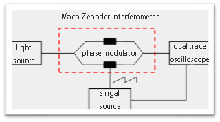
The method is applicable to the low-frequency lower half-wave voltage test of the phase modulator and the intensity modulator. The test principle is shown in Fig. 1.
Figure 1 Schematic diagram of the half-wave voltage test system
When the electric field V(t) is applied to an interfering arm of the Mach-Zehnder interferometer, the input light field produces a phase shift φ(t) on the arm due to the electro-optical effect. For the light field with the input Ein(t), The output light field function is:
Eout=Ein(t)cos【φ(t)】=Ein(t)cos【πv(t)/vπ】 (1)
Where Vπ is the half-wave voltage of the phase modulator on the arm. The curve of the output light field with voltage is shown in Fig. 2. It can be seen that the voltage variation corresponding to the half cycle of the sinusoidal signal is the half wave voltage.

Fig. 2 Variation of output light field with voltage of Mach-Zehnder interferometer
Mach-Zehnder Interferometer: The half-wave voltage test method differs from the extreme value method in that instead of a DC signal, a sawtooth signal is applied to the phase modulator, which avoids external factors (such as temperature changes, vibrations). Etc.) The effect of random phase changes. Use an oscilloscope to track both the sawtooth and output optical signals. The half-wave voltage can be calculated by comparing the periods of the two signals. This method avoids the error of the extreme value judgment in the extreme value measurement method and improves the measurement accuracy.
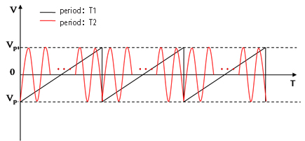
Assuming that the phase modulator is loaded with a sawtooth signal with a period of T1, the period of the output sinusoidal signal is T2, and the signal shown in Figure 3 can be detected on the oscilloscope. According to the half-wave voltage formula (2) described in Section 3.2, it can be concluded that:
Vπ=VPP /2*(T1/T2) (2)
Where Vpp refers to the peak-to-peak value of the sawtooth wave, ie Vp+ - Vp-.

Figure 3 oscilloscope output signal
2. Use square wave signal to measure half-wave voltage
This test method is suitable fror the intensity modulator half-wave voltage test. If the phase modulator is tested, the MZ interference system test can be built. The schematic of the method is as follows:
 />
/>
Figure 4 Square wave signal half-wave voltage test schematic
Note: (1) The modulator needs to adjust the bias point voltage to work in the linear region and ensure that the detector works in the linear region;
(2) The signal source output impedance needs to match the impedance of the modulator RF terminal (50 ohms).
Connect the system as shown in the figure above. The Vpp is gradually increased. We can see on the oscilloscope that the amplitude of the square wave signal increases with the increase of Vpp, then reaches the maximum value, and continues to increase Vpp. The square wave shows distortion on the oscilloscope. The Vpp value is recorded until the situation as shown in Fig. 5(c) appears.

(a) Vpp=0 (b) Vpp reinforce (c)complete distortion
Figure 5 oscilloscope output waveform changes
At this point, the RF half-wave voltage can be calculated according to the following formula:
Vpi=Vpp/2 (3)
Note: If the signal source output is high impedance, the voltage applied to the modulator is approximately 1/2*Vpp, and the half-wave voltage should be multiplied by 1/2.
The above two methods are suitable for the low-frequency lower half-wave voltage test of the modulator. The high-frequency lower half-wave voltage test method can refer to the following two documents, which will not be described in detail here.
1. Wei Zhengjun et al. Measurement method of the half-wave voltage of phase modulator based on Sagnac fiber interferometer[J], Optics, 2011, 31(6).
2. Jia Yupeng, et al. Half-wave voltage measurement of intensity modulator based on spectral analysis[J], Journal of Beijing University of Technology, 2015, 41(12).