
characteristic:


Operation steps:
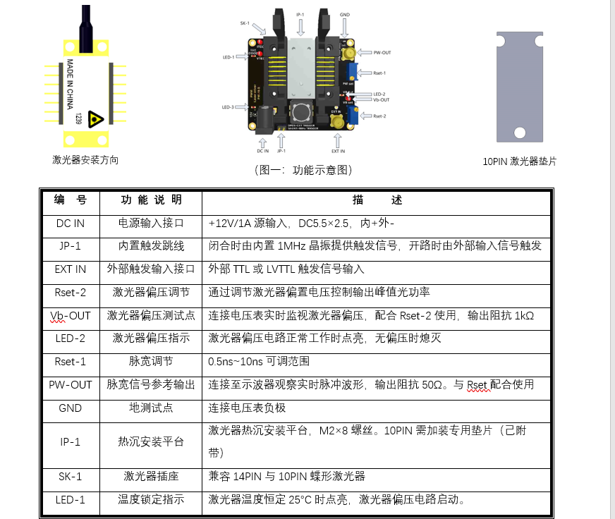
1. Do not install laser when power on for the first time. Use jumper cap to the short circuit "JP1" or connect "ext in" through the external signal source. Input a low-frequency TTL or LVTTL signal (10kHz ~ 1MHz) to trigger the driver.
2. Connect "PW-out" to an oscilloscope, connect the power supply to "DC in," observe oscilloscope pulse waveform. Adjust "reset-1" to determine whether the pulse width is in the range of 0.5ns ~ 10ns. If normal, please adjust the pulse width to slightly less than the target value.
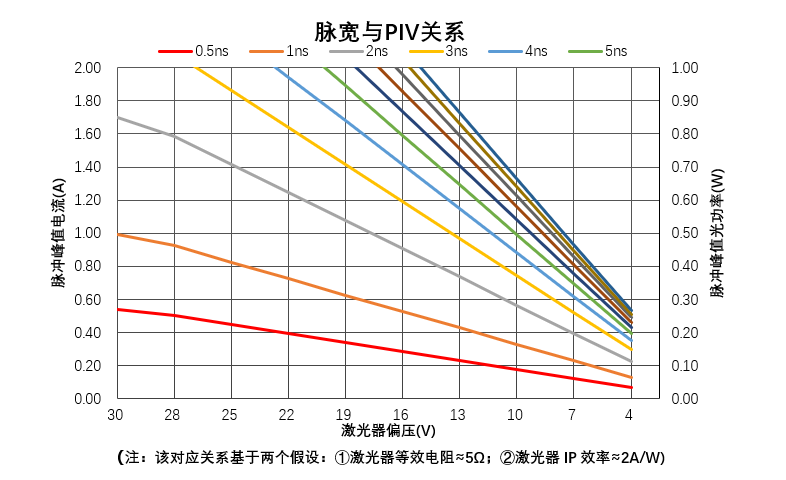
3. Disconnect the power supply, disconnect the "JP1" jumper, and disconnect the "ext in" input. Make sure that no trigger signal is input into the driver, then install, fix, and power on the laser. When the laser temperature is stabilized to 25 ° C, "led-4" lights up. Connect the voltmeter to "VB out" and "GND," adjust "set-2", observe the reading change of the voltmeter, and adjust the range: 4V ~ 30VDC. According to the corresponding relationship between pulse width and PIV given in the figure below, VB voltage is determined by combining target pulse width and target peak optical power. (you can also start directly from the lowest voltage).

4. Adjust VB to the target value with a value lower than 30% or directly take the lowest voltage, and then disconnect the power supply. Connect the "JP-1" jumper cap or external signal source to "ext in," and the trigger signal's initial value shall be as low as possible, such as 100kHz.
5. After the power supply is turned on and the led-4 lights up, the system enters the normal working state. At this time, the pulse light signal can be observed through the optical power meter and photoelectric detector. Further adjust the repetition frequency, pulse width, and bias voltage as needed until the output power and pulse width reach the target and the operation process ends.
Maximum working range and working principle of protection circuit:
The maximum pulse peak current provided by the driver is ≈ 2a, which may damage the driver. So don't try a peak current higher than 2A. The maximum pulse peak current that the laser can bear is different, and it has a large proportion with the pulse width and repetition frequency. Generally, when the repetition frequency is low, and the pulse width is narrow, the maximum pulse peak current that the laser can bear is larger.
To avoid laser damage caused by cathode short circuit or anode overvoltage, CW current limiting point of 100 Ma is set. While protecting the laser, it also limits the pulse current. Maximum pulse current = repetition period △ pulse width × 100mA. Laser temperature protection principle: only when the internal temperature of the laser is stable at 25 ° C, "led-4" lights up, and "VB" has voltage. Otherwise, the bias circuit does not work, and the output is zero. When the laser loses temperature, the bias circuit stops supplying current to the laser immediately. The driver also provides input reverse connection protection and surge protection. The principle is not detailed here.
For higher performance, that can select the laser welding version.
Description of common problem:
Due to different lasers' different responses to pulse current, waveform problems may occur, such as slow rising edge and high-level oscillation. In addition to the laser itself's stray inductance and the package capacitance's series effect, light reflection may cause the above two situations. When the peak power approaches or exceeds the upper limit of nominal CW power, the above two problems may occur under a long pulse. Usually, there is a visible critical point, which shows that the light power no longer increases or decreases with the increase of current. Take cm96z series laser as an example

It can be seen that it is expected when the pulse is narrow. For a long pulse, when the peak current is more significant than the nominal CW rated current, the waveform oscillates, the current driving doubles and the output power only increases by 30%. The oscillation mainly comes from the reflection coefficient of the lens, fiber coupling, and FBG grating. The performance of different series of lasers is quite different. In this case, the corresponding relationship between pulse width and current can be adjusted to find a good balance point.
The correlation of pulse width, repetition frequency, and the peak current is challenging to balance perfectly due to laser difference. The typical default circuit is set to 10ns pulse width, and the peak current does not follow the repetition frequency in the range of 50 Hz ~ 1 MHz. The duty cycle of 1% or less is recommended in the field of 0.5ns ~ 10ns. The smaller the duty cycle is, the smaller the effect of PRF is.